Friday, February 8, 2013

2004 Sienna Timing Belt/Water pump notes.

2004 Toyota Sciena timing belt and water pump removal and installation notes:

There are more complete web sites and video's of this procedure, but I wanted to document a few points I figured out.

First of all see my post regarding the side mounting bracket flaw.

Next, the engine is mounted so close to the side wall of the engine bay that removing the rear cam gear to take off the timing belt cover back is difficult without the special tool to hold the cam gear.  My solution was to not remove the rear timing gear and only loosen the rear cover so the water pump could be removed.  I did this by removing the front timing gear with a powerful torque wrench.  I then removed all of the bolts to the rear timing gear cover.  The bolts behind the rear cam gear are accessible by rotating the cam.  Do not be surprised when the cam gear springs uncoils and spins a bit. Just make sure you line up the timing marks and you will be fine.  Once you get all of the rear timing gear cover bolts removed, it can be rotated around the rear timing gear so the water pump can be removed.  It only needs to rotate a little to make way to slide out the water pump.

The other thing worth mentioning is that the crankshaft timing mark is on the top side of the crank.  See my picture below.

The best tip ever from another site was to use electrical ties to hold the timing belt on the cam gears during installation.  The rear cam gear and belt is nearly impossible to line up, so rotate it so you can see it, and then attach the electrical or zip tie around the cam gear and timing belt.  Once you have the other marks lined up simply cut the zip ties.


2004 Sienna Side Engine Mounting Bolts, Design Issue


Ok, so I completed changing my timing belt on my wife's 2004 Sienna mini van.  Just prior to this, I replaced the timing belt on the 98 Sienna.  The design of the newer van although a bit more stylish than the 98 has been given a few design flaws.  Hopefully this blog will help others deal with the problem and maybe drop the hint to Toyota to fix this in the next version.  Even with a few design flaws, it is far superior to most other cars, I have had the pleasure of fixing.  

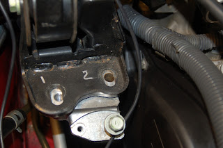
The flaw, I would like to mention today is the side mounting bolt bracket assembly.  The side mounting bolts sit just in front of the top timing belt cover on the side of the V6 engine on the passenger side.  They are used to connect the engine to the top of the area close to the strut tower.   The bracket is composed of 2 aluminum pieces stacked on top of each other.  The lower one bolts to the side of the engine.  Two long vertical bolts thread into this piece.  A shear pin is located between the bolts to keep the spacer bracket from sliding.  The upper aluminum spacer bracket has two clearance holes.   Also there is an additional threaded hole in the top of the bracket labeled #1 below.  A final black steel bracket rests on top of the middle piece.  The vertical bolts sandwich the 3 brackets together.

This design is nearly the same as the 98 with a couple exceptions.  The outside of the black metal bracket is dished up.  Picture below shows the bracket with clearance holes labeled 1 and 2.  I am guessing this provides extra rigidity.  Unfortunately, it acts as a funnel to route water and debris into the clearance holes for the vertical bolts.  The bolt heads do not completely cover the slotted holes in the metal bracket.  The slotted holes feed directly into the clearance holes in the middle bracket, which direct everything into the threaded lower bracket.  

So I discovered this problem when trying to take the mounting bolts out.  The front bolt came out with a significant amount of torque.  The rear bolt failed in torsion, even after soaking it with PB blaster.  Not only did the the bolt fail in the middle of the non-threaded shank, the middle aluminum bracket was still attached to the lower bracket.  Crud in the clearance hole and remaining stud was holding onto the middle bracket.  I ended up working it back and forth and twisting it around after raising it over the shear pin enough to get it loose.  Once I removed the spacer section, I removed the lower bracket with the remaining broken bolt end attached.  See picture below of the lower bracket with the sheared bolt attached.   I put the bolt in my vice and turned the bracket and luckily was able to remove the bolt without damaging the lower bracket.  

Se pictures of the bolt below.  Note that this bolt came out of a suburban driven van, that is kept fairly clean.  

To avoid the problem again, I would consider putting a small amount of RTV sealant in the slotted holes on the metal bracket.  Also, I would grease the mounting bolts prior to installation.  

Upper Bracket
Middle Spacer Bracket

Lower Bracket with Broken Bolt attached.
Lower Bracket


Crud around the threads on the long bolt

Monday, January 9, 2012

92 95 Honda Civic Instrument Cluster Short in Dashboard Brightness Controller

Was going to make a great blog about how to fixed cracked solder joints in my Dashboard Brightness Controller by reflowing the solder.  Unfortunately my re-solder efforts did not fix the problem.  The problem seemed to be a cracked solder joint because initially, I was able to push on the side of the variable resistor wheel and have lights until I let go.  I tried to reflow the connections of the variable resistor but that did not seem to help.  I tested the circuit for continuity and it seemed ok.    Until I figure out a better way, I will give you the cheap work-around fix.

Please feel free to comment if you know what goes wrong with these circuits and what needs replaced or re-flowed.

On the 92-95 Honda Civics the dashboard dimmer, moon roof control and cruise on and off buttons are housed in a plastic assembly to the left of the steering wheel.   This assembly can be pried straight out with a screwdriver or in my case a key.  Once the assembly is out, there are two plugs in the back of mine, three if you have a moon roof.  These can be removed by squeezing the tab at the back of the connector and pulling out.  In my case the green one goes to the cruise control and the grey one goes to the dashboard brightness controller circuit.  

There are three wires going into the back of the grey connector.  The middle one is black.  One is red and another is red with a black stripe.

The quick fix is to connect the black middle wire to the red wire, using a paper clip. Cut a small paperclip such that it is shaped like a "U" and about 1/2 inch tall.  Push the ends of the paper clip into the front side of the connector.  One end, push into the middle and the other goes to the red wire.  I placed electrical tape over the paper clip and connector, to hold it in place and stop it from shorting out anywhere.  I pushed the connector back into the dash, reconnected the green connector to the cruise control and then shoved the entire assembly back into the dash.  This eliminates any dimming capabilities and everything is at full brightness.  For me I don't ever want to dim the lights so that did not matter.  I would like to solve the problem, the right way, so let me know if you have any ideas.

BTW, in the process of experimenting, I blew the #19 10amp fuse that feeds the controller.  Luckily the Honda Engineers put in a fuse puller and an extra fuse in the fuse box under the dash, so this was an easy fix.

Tuesday, March 15, 2011

2004 Sienna Key fob receiver repair Solved 2005 2006 2007 2008 LE XLE CE

My wife had the reciever go out on our 2004 Toyota Sienna. After about 2 hours of searching I found the following fix. This worked and was the only reference I found. I have added some details to the fix. Please read the following before moving away from blog.

I did the procedure at the link below on my 2004 Toyota Scienna XLE and it worked great.  My wife thinks I am genius.

The way to get your van to respond to the key fob is to unplug a wire behind the radio and plug it back in.

Anyway a couple things to add. 
Unplug the communication wire behind the radio. More specifically the receiver is a white plastic box about 3x3x1 inches. There is only one connector going into the white housing. It has five wires in the one connector. Right above the transmitter is another larger box with about 4 connectors going into it. When I pulled the communication wire out it felt a little loose. I suspect that it had vibrated loose.

Toyota stealer wanted $90.00 just to inspect the system.

Lastly, the way you know the problem is with the receiver (Part on the vehicle) and not the key fob is that your doors will not lock and unlock after completing the re-programming sequence. This was only obvious to me after a few runs through the programming sequence with no response. I figured out that the sequence does not even use the key fob up to that point.  The programming sequence is just a long series of doing things any driver does on a regular basis, unlocking doors, turning the key, opening doors.  No degree in computer science is required.

One more thing, I found a great video for the programming sequence, for those who hate reading directions
http://www.youtube.com/watch?v=bD0RvPC-7bc

How to remove radio video is below. These directions are great, except for a couple of things. One you can use a butter knife to pry out the panels. No need to buy the special tool. The other thing is you do not need to remove any connectors from the radio or side panels. Just place everything to the side with wires attached.

http://www.youtube.com/watch?v=flCsB8sOBdk

Thanks to all!!

Reference to the Receiver Solution Below
http://www.tomshardware.com/forum/45-64-working-2004-sienna

Sunday, September 19, 2010

98 Toyota Sienna Van Tail light Replacement. Also Dome light replacement

To replace the brake and turn signal bulbs the entire assembly must be removed. Each assembly is held in by 2 bots and 2 pins

The two bolts are 10mm. The plastic pins that are also holding in the assembly are perpendicular (90 degrees) to the bolts. When prying, pry the assembly away from the side of the car(perpendicular to the axis of the bolts) Pry a little at the top and then switch to the bottom and repeat until the pins pop out. Be carefull not to bend the plastic flap where the bolts are attached.

The lights are Philips numbers 1156 and 1157. Replace all of them.

The Dome lights are covered by a small plastic lens. This pops out with a screw driver. Be careful because the tabs will break easily. Pry the tabs on the ends closest to the sides of the vans first. Press toward the light. It should swing down. Now gently ease out the side snaps.

Saturday, May 1, 2010

Replacing HID ballast or computer control lighting for the Headlight

Just got a 2004 Sienna XLE limited with 60k. The wife noticed one headlight would turn on and then flicker and go out. So I was thinking 10 bucks and 5 minutes and I would have a fixed light bulb. Think again. Turns out my new fancy Sienna has a special light called HID (High Intensity Discharge) Xenon. Up until now, I did not know I had the option of seeing twice as far with Xenon. Also up to now, I am not sure that I cared to see that far. 

Bulbs costs 100.00 from Autozone and must be ordered. So I found some on ebay 20.00 with free shipping and replace both of them as advised.

http://stores.ebay.com/HID-Xenon-World

So I tried them out. Light comes on, light flickers then goes out, same problem. I search the internet a little more and found out I could have a bad ballast or a bad connection. I cannot see any connections, because the connections are buried under the housing assembly. So how much is a ballast? Or as Toyota calls them computer lighting control. From the dealer expect to pay $600.00 - $900.00. That's right, almost what I paid for my last two cars. All that, just to help me see 2X farther than I am probably capable in the daylight.

Back to e-bay. I ended up buying a used ballast about $40.00. The OEM is made by DENZO. The original was DLT002 but I read somewhere that you could use part# 'KDLT002'. On the part it is printed that it is only supposed to last 2000 hours. Hopefully not too many of those hours have been used.

I got the part and then checked out my repair manual. To get to the ballast out, you must remove the front bumper. That's right the front bumper cover must be removed to get to the screws that hold on the light assembly. The ballast is located on the bottom of this assembly.

To remove the bumper cover you must remove the 4 black plastic plugs at the top of the bumper. These have a solid black head that is pushed into a black nut. These can be removed by prying up on the head with a screw driver. Pull the head up about 1/4 of an inch and then pry the lower part out. It should come out very easily.

Next unscrew the 6 screws the bottom side of the bumper next to the splash screen. On the far side of this bumper are square light colored plastic inserts that both capture the splash shield and provide a place for a screw. These need to be squeezed from the back if possible, after the screws are removed. They should snap back through.

Also the fender well splash shields have 3 types of fasteners that must be removed. The fasteners toward the rear are black and square and have a screw in the middle. Remove the screw. The square must be pried out a little bit and squeezed from the back if possible. They have snap fits on the corner of the square shaped insert. I broke a couple of these.

There are a couple snap fit fasteners with the solid head black in color as described previously. These are located at the top of the wheel well. Toward the front of the wheel well is a fastener with a slotted head. The head seems to pry straight out.

Lastly there are a couple fasteners toward the back of the wheel well that simply unscrew.

Now the fun begins. A bolt between the front bumper cover and the fender must be accessed from the inside. I had to find a 10mm boxed end wrench that was slightly offset before it would move. Once this bolt is removed, release two square black snap fits with a small screwdriver to release the bumper from the fender. These are located midway between the center bolt and the edge. Use a small flat head head screw driver to depress the snap fit on both square snap fits.


Now the front bumper dropped far enough away to get to all the bolts on the headlight assembly. Remove all of the mounting bolts and the headlight wires.

After removing the assembly, I found out that ballast had been badly corroded. Probably, water was pooling the ballast area.


The new part fit nicely in the same location.  I cleaned out the corrosion from the housing and seal.


Install all the wires to the light assembly before installing the fixture.


In the end after buttoning everything up, the light did work fine.

If anyone figures out a way to switch back to the non-HID version please comment below. Hopefully this helps someone else avoid some headaches.  Also, feel free to add to advice that might help.

2014 Update: After several years the light on the other side is no longer working.  The side I replaced is still working.

Also it appears that in order to change back to Halogen lights I would need to buy a new light fixture.  This is still very tempting, as I have been less than impressed with the HID light fad and expensive Ballasts.