Ok, so I completed changing my timing belt on my wife's 2004 Sienna mini van. Just prior to this, I replaced the timing belt on the 98 Sienna. The design of the newer van although a bit more stylish than the 98 has been given a few design flaws. Hopefully this blog will help others deal with the problem and maybe drop the hint to Toyota to fix this in the next version. Even with a few design flaws, it is far superior to most other cars, I have had the pleasure of fixing.
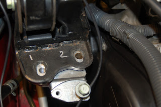
The flaw, I would like to mention today is the side mounting bolt bracket assembly. The side mounting bolts sit just in front of the top timing belt cover on the side of the V6 engine on the passenger side. They are used to connect the engine to the top of the area close to the strut tower. The bracket is composed of 2 aluminum pieces stacked on top of each other. The lower one bolts to the side of the engine. Two long vertical bolts thread into this piece. A shear pin is located between the bolts to keep the spacer bracket from sliding. The upper aluminum spacer bracket has two clearance holes. Also there is an additional threaded hole in the top of the bracket labeled #1 below. A final black steel bracket rests on top of the middle piece. The vertical bolts sandwich the 3 brackets together.
This design is nearly the same as the 98 with a couple exceptions. The outside of the black metal bracket is dished up. Picture below shows the bracket with clearance holes labeled 1 and 2. I am guessing this provides extra rigidity. Unfortunately, it acts as a funnel to route water and debris into the clearance holes for the vertical bolts. The bolt heads do not completely cover the slotted holes in the metal bracket. The slotted holes feed directly into the clearance holes in the middle bracket, which direct everything into the threaded lower bracket.
So I discovered this problem when trying to take the mounting bolts out. The front bolt came out with a significant amount of torque. The rear bolt failed in torsion, even after soaking it with PB blaster. Not only did the the bolt fail in the middle of the non-threaded shank, the middle aluminum bracket was still attached to the lower bracket. Crud in the clearance hole and remaining stud was holding onto the middle bracket. I ended up working it back and forth and twisting it around after raising it over the shear pin enough to get it loose. Once I removed the spacer section, I removed the lower bracket with the remaining broken bolt end attached. See picture below of the lower bracket with the sheared bolt attached. I put the bolt in my vice and turned the bracket and luckily was able to remove the bolt without damaging the lower bracket.
Se pictures of the bolt below. Note that this bolt came out of a suburban driven van, that is kept fairly clean.
To avoid the problem again, I would consider putting a small amount of RTV sealant in the slotted holes on the metal bracket. Also, I would grease the mounting bolts prior to installation.
 |
| Upper Bracket |
 |
| Middle Spacer Bracket |
 |
| Lower Bracket with Broken Bolt attached. |
 |
| Lower Bracket |
 |
| Crud around the threads on the long bolt |


